


|
|
|
|
|
|
||||
|
|
|
||||||
|
|
|
|
||||||
 |

To gain maxium benefit and use from this
product, |
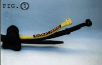
STEP 1
|
|
 |
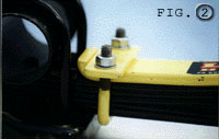
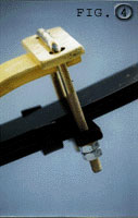
STEP 2Place one of the Load Hog™ blades on top of
the rear half of |
STEP 3
|
 |
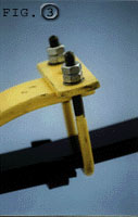 |
STEP 4
|
 |
STEP 5Lower the vehicle to the floor and re-check
the tightness of the inner U-bolt nuts, ensure brake pipes
and |
||
|
LoadHog™ Helper springs should take
approximately 20 minutes to fit. |
! CAUTION ! |
©ĀLOADHOG™ĀSA.PAT.NO.99/5174
| KYLE WARD |
|
WEB DESIGN |